CE-2800 Embedded Systems Software
Lab 3: Bouncing Light
Objectives
- Become familiar with assembly language program design and instructions
- Use assembly language branch instructions to implement conditional logic
- Use assembly language instructions to initialize and use the Stack
Pointer for subroutines.
- Use assembly language to implement and call subroutines.
Assignment
In this lab, you will create a "bouncing LED" program (did you ever
see the "Knight Rider"
TV series? It's OK if you didn't - it was stupid). Specifically, your program must:
- Begin by lighting LED 0.
- After waiting for exactly X ms, light LED 1 and turn
LED 0 off. X is the number of 10*(number of chars in your MSOE
email name) milliseconds. Thus, if your email name has 7 chars, the
delay must be 70ms.
- Continue "moving" the lighted LED every X milliseconds. After LED
7 is on, start moving the lighted LED position in the opposite direction in
the next step.
- When LED 0 is reached, start moving back in the other direction once
again.
- Repeat this forever.
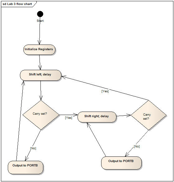
Here is a flowchart to help you visualize the logical structure of the preceding sequence:

Design constraints:
- Use the program structure you used in the previous lab, with the various
sections clearly delineated and commented.
- Never allow all the LEDs to be off at any time (not including the Power
LED), except for a few microsecond delay as the circuitry is activated and
deactivated.
- Use bit-logic instructions (LSL, LSR) to manipulate the
bit contents of a single register that represents which LED is lit.
- Use a time delay loop (like the one discussed in class), but use a
triply-nested loop based on the
DelayLoop sample
(on the course website) to achieve the exact required delay. You'll
have to adjust the values of C1, C2, and C3 to achieve this, as well as
adding a few NOP instructions. Note: Minimize
the use of the NOP instruction in "fine-tuning" your loop.
- You must implement the delay loop in a subroutine - NOT
embedded in the "main" body of your program. When computing values for C1,
C2, and C3, don't forget to adjust the formula to include the number of
cycles it takes to RCALL the subroutine and RET from it!
- You will need to implement several labels for jump targets (always use
labels for jump targets; never use raw addresses). Use meaningful names for
your labels.
- Define meaningful names for the registers you use, and subsequently
refer to the registers by these names in your program.
- Comment your code heavily.
Hints:
You can use the
DelayLoop
sample from the course website as a starting point; however, you will have to
incorporate the delay code as a subroutine from the "main" body of code.
Use the LSR instruction to move the LED position to the "right" (for
example, from LED 7 to LED 6). After
each shift, use a branch instruction that tests to
see if the bit you shifted was shifted into the Carry bit. (Note: the DelayLoop sample code uses a branch instruction that tests the
Zero bit, not the
Carry bit, so you cannot use that code directly) Similarly, to move to the
left, use the LSL instruction, each time testing to see if the
bit was shifted into the Carry bit.
As an option, you may implement and use additional, separate subroutines to
handle moving the LEDs to the right and left. You must however, still implement
a single delay subroutine.
Demonstration
You must demonstrate your working program on your board, with the
oscilloscope measuring the period of either LED 1 or LED 6. Develop and debug
your program in AVRStudio first (its' easier that way). It may be helpful to set
the AVRStudio Simulator clock speed to 8MHz, and adjust your timing loop to
result in a delay that is twice that required when it runs on your 16MHz board.
Lab Submission (due 11:00pm, Tuesday, January 3)
For your submission, prepare a report in Microsoft Word format.
Be sure that you answer the following question in your report.
- What values for constants C1, C2, and C3 are needed to result
in the required delay
loop?
- Show how these values, when used in the formula found in the DelayLoop
comments, correspond to the required delay time in milliseconds.
- How many NOP instructions did you have to add?
Copy/paste your program's instructions from the .lst file generated by the
Assembler into your report.
Include both the Word report and your program (.asm
file) in your submission.
Upload your submission through
Blackboard (assignment "Lab 3").
Be sure to keep copies of all your files, in case something gets lost.
Grading
Your lab grade will be determined by the following
factors:
Report - content, spelling, and grammar (use the
built-in spell checker)Program - comments and formatting are important
aspects of assembly language programming! And it has to work correctly.
Timeliness of
submission as stated in the
course policies.

