CE-2800 Embedded Systems Software
Lab 10: Sound Synthesizer - Part 2
Objectives
- Become familiar with assembly language program design and instructions
- Use assembly language branch instructions to implement conditional logic
- Use assembly language instructions to implement subroutines and
subroutine calls
- Use device driver subroutines to initialize and read the keypad
- Use the EEPROM subsystem of the Atmega32 to read and store data to
persistent memory
- Use the Watchdog timer subsystem of the Atmega32 to trigger a system
reset in certain conditions
- Use the MCUCSR register to determine the reason for a system reset
Assignment
In this lab you will add functionality to your Sound Synthesizer you developed
in Lab 9, such that your program will incorporate the Watchdog Timer to trigger
a system reset when no keys on the keypad are pressed within a specified period
of time. That is, when the keypad is left idle, the system will reset.
Additionally, you will include the LCD display in your software to display the
number of times each type of reset (Power-on, External Reset, or Watchdog
Timeout) occurred.
Note: No interrupts need to be used for this program.
Hardware Configuration
- PortB configured for digital output.
- Keypad connected to PortA.
- Piezo speaker connected to OC0 (PB3).
- LCD display connected to USART.
Program Functionality
Your "main" program should be
placed in the file named Lab10.asm.
You
must implement the following additional functionality:
- Whenever the system resets (through power-on, external reset button
press, or Watchdog Timer reset), your program should check the bits in the
MCUCSR register to determine the reason for the reset. Note that you must
clear the bits in MCUCSR after each reset, since only the Power On reset
clears other bits. If you don't clear, the MCUCSR will report multiple
reasons for reset.
- Each time a reset occurs, your program must increment one of 3 bytes in
EEPROM that track the number of resets for each reason.
Thus, upon each reset, you must read the previous value of the reset count
stored in EEPROM, and then write the incremented count back to EEPROM. Note
that initially, you should define these bytes to all have values of 0.
- Your program must display the number of resets that occurred (since the
program was loaded to your Atmega32 board) by reading all 3 bytes of EEPROM
memory that maintain the number of resets for each reason. On the LCD, you
should display something like the following: Pwr: 0001 Ext: 0004 Wdg: 001E.
You may have to arrange the output to appear on both lines, since it may not
all fit on one line of the LCD.
- Whenever the keypad is left idle (that is, no keypress is made) within a
specific amount of time (set it up for ~2 seconds as in lecture), the
Watchdog Timer should trigger a Watchdog reset.
- Optional: Beep the speaker differently on each type of reset.
Notes on configuring AVRStudio for EEPROM downloading
The default configuration for your Atmega32 and AVRStudio causes EEPROM to be
erased every time you download a program or start a debugging session. You can
change these defaults with by doing the following:
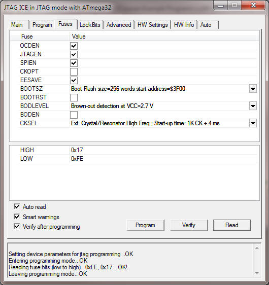
In the Connect dialog of AVRStudio, on the Fuses tab, check the EESAVE
checkbox (shown below):

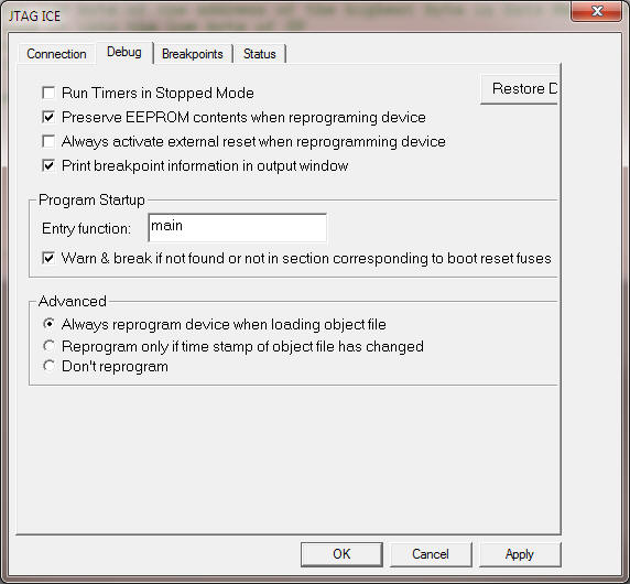
During debugging, select Preserve EEPROM contents when reprogramming
device on the Debug tab:

Demonstration
You must demonstrate your working program on your board by the end of
the lab in order to receive credit for it.
Lab Submission (due by end of lab, Thursday, February 16, 2012)
For your submission, you need only supply your working, fully commented
Lab10.asm.
Upload your submission through Blackboard (assignment "Lab 10").
Be sure to keep copies of all your files, in case something gets
lost.
Grading
Your lab grade will be determined by the following
factors:
Program - comments and formatting are important
aspects of assembly language programming! And it has to work correctly.
Timeliness of
submission as stated in the
course policies.


