CS-321 Lab 6
Transformations in 3 dimensions
Overview
This is a 1-week lab.
In this lab, you will be integrating the 3-D transformation methods (for
rotation, translation, scaling, and perspective) you have
learned about in class recently into your existing GUI application (from Lab 5).
Once you incorporate 3-D transformations into the program, you will be able to
display shapes from any point of view.
The 3-D transformations will be carried out via the ViewContext object that you
created in Lab 5; however, you will have to extend the ViewContext class to
operate on 3-D line data, rather than 2-D as before (more details below). You will
also be modifying your GUI one more time to accept user-specified viewing
parameters like those discussed in lecture. Based on this user input, the ViewContext will internally set up the necessary
3-D transformation pipeline that applies rotation, translation, and scaling for converting
from one set of coordinates to another (from model coordinates to viewing
coordinates to window/device
coordinates). Furthermore, the ViewContext object will apply a perspective
projection (as an additional transformation) as part of computing the viewing
coordinates.
You will NOT
have to provide the functionality to create or modify images via mouse input in
Lab 6, so you will not have to provide a conversion from mouse coordinates to model coordinates.
You will NOT have to modify any derived shape class except for the line
class. Details below.
Activities
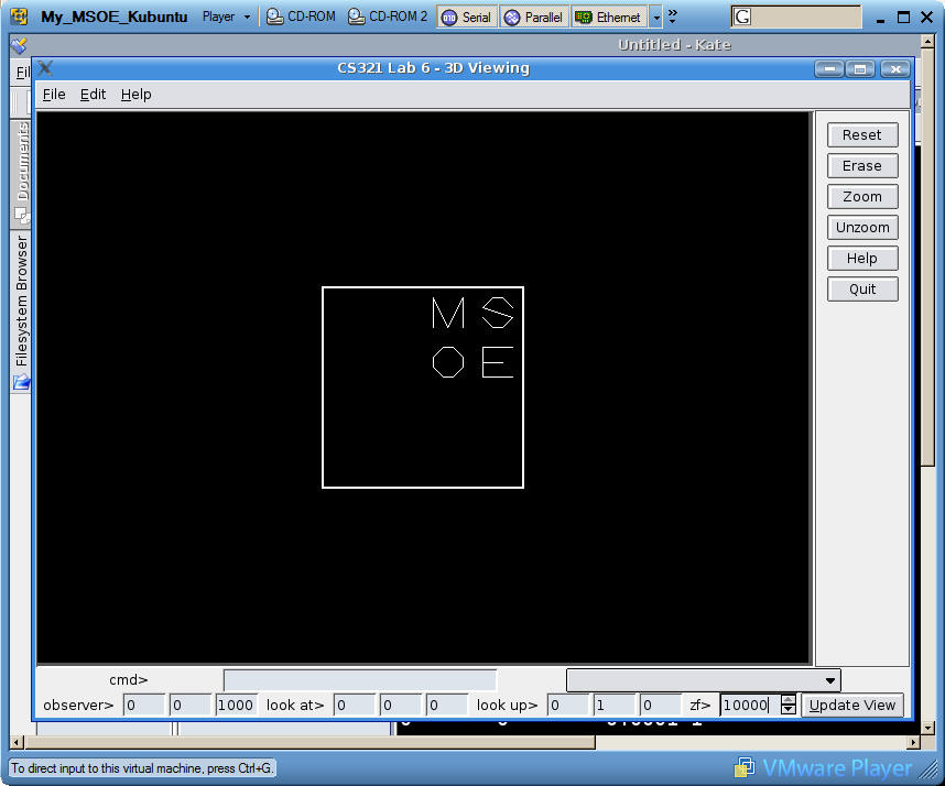
- Create a modified GUI interface that allows the user
to specify and change individual viewing parameters - see the figure below.
Your new interface must allow the user to specify the observer position (the
point the observer is looking from), the point the user is looking at, and
the look-up direction. You needn't remove
the Rotate & Pan controls that you developed for Lab 5; in fact, you can use
these for extra credit - see below.
- For the perspective projection, you must also provide
a user interface capability to specify the distance to
the focal point from the observer (which is the zf value in the lecture
material).
- Extend the ViewContext class to incorporate
transformations for model-to-view, view-to-device, scaling, and perspective. Here is the UML
class diagram illustrating the relationship between the classes, including
the updated ViewContext class with the specific methods you need to
implement:
Note that you may leave the methods and attributes from Lab 5 in your ViewContext class,
but you won't be using those methods anymore. Instead you'll be implementing
and using the four new methods shown. The
suggested way of handling 3-D coordinates is with a new class (_3DVector)
that you must implement - there is no readily available Qt class that you
can take advantage of.
It is suggested that you encapsulate and maintain four 4x4 transformation
matrices within your ViewContext class - one each for the model-to-view,
view-to-device, scaling, and perspective transformations.
The view-to-device matrix is essentially constant and can be formulated once upon construction of
the ViewContext object, using the values for your viewing window width and
height.
You should reform the model-to-view
transformation matrix as well as the perspective matrix based on changes to
the viewing parameters entered into the GUI and after the UpdateView button
is pressed. Use the setView method to set the viewing parameters and use the setPerspective
method to set the perspective parameter.
The scaling matrix is reformed within the setScale
method, which should be called whenever the Zoom/Unzoom buttons are pressed
(as in Lab 5).
Each time any of these four methods is called, the overall
compound transformation matrix should be formulated as the product of the
four individual transformations. The overall transformation matrix is then used to transform model coordinates to device coordinates when it is
time to draw the image.
- To support 3-D models, the simplest approach is to
modify your line class to support 3-D data, including reading 3-D data from
a file. If you're using QPoint objects now to hold 2-D data, you'll have to
replace QPoint with the _3DVector class shown above, which you need to
write. If you're maintaining endpoints with scalar x1, y1, x2, y2 variables,
you'll just have to add z1 and z2 variables. You'll need to modify the
line::Read method to read a file containing 3-D line information instead of
2-D information. You don't need to save the files, so you won't have to
modify line::Write().
To repeat: None of the other classes (point, polygon, bezier) need to be
modified, since they won't be used in this lab.
The file msoe.dat contains coordinates for a
3-D shape described as a set of lines; i.e., there are two 3-D points per line. You may find it necessary to edit
the format of these
files to conform to your Read implementation. While you may change
the file format, do not change the values of the coordinates within the
files.
- Here are some examples
of what your image should look like for various values of observer position,
lookup vector, and lookat positions
Extra Credit Activities
- (10 pts) Use the pan up/down/right/left buttons from
Lab 5 to modify the observer's position (the "look from" point) by
panning the view Left/Right in the x direction and panning Up/Down in the y direction
of the viewing coordinate system. This is trickier than it sounds,
since you have to determine the direction of the vectors in the model
coordinate system that correspond to the the view's sense of right, left,
up, and down. Hint: The "view-up" vector you specified in the model system
is the sense of the "up" direction in the view system.
- (10 pts) Use the Rotate CW/CCW buttons from Lab 5 to
modify the observer's position by rotating the observed position about the
view-up vector. This will result in a kind of "fly-by" effect. This involves injecting yet another transformation matrix as
the first in the pipeline - the transformation for rotation about an
arbitrary axis, whose form is as follows (where the vi are the
normalized components of the view-up vector):
All code implementing the extra credit functionality must be (as usual)
well-commented and discussed in your lab report.
Hints
- Your images will automatically appear basically
centered on your screen if you correctly formulate the view-to-device
transformation, which places the view coordinate frame at the center of
your screen. No "auto centering/auto scaling" need be implemented in
this lab.
Demonstration (during week 10 lab)
You will need to demonstrate your completed project by end
of lab week 10. If late, you must demonstrate no later than 4pm Friday of week
10.
Lab report (due Friday week 10)
Submit your assignment following these instructions:
-
In addition to your
Word report file,
I want all .pro, .cpp, and .h files.
Use
webCT to
submit your
assignment ("Lab 6").
Zip the files
for ease of submission (but be sure to use the zip format).
- Record the time (in minutes) you spent on
this lab in the FAST system for week 9.
Be sure to keep copies of all your files, in case something gets lost.Your lab grade will be determined by the following
factors:
Program quality
- Meeting requirements/correct program operation/output.
- Technical quality (comments, formatting, naming)
Report quality
- Required content
- Spelling and grammar (your word-processing program has
a built-in spell checker
- use it)
- Timeliness of submission as stated in the
course policies.
If you have any questions, consult me.