Appendix A: Sample
Laboratory Exercise
Electrochemical Cell
(Battery) Experiments (Version 1.0)
BE-103, Winter
'00-'01, Dr. C. S. Tritt
Introduction and Background
In these experiments, you will perform a series of tests on
two brands of primary electrochemical cells (batteries). You will then compare
the results of these tests to the IEC standards and manufacture’s claims. A
clear limitation with these experiments is the single set of discharge
conditions. Many more sets of conditions would be required to draw definitive
general conclusions about the relative performance of the two brands of
batteries investigated.
Electrochemical cells are referred to commonly, but
incorrectly, as batteries. Electrochemical cells, or simply cells, are units
consisting of a positive electrode (or anode) and a negative electrode (or
cathode) separated by an electrically conductive and chemically reactive
electrolyte. Technically, a battery is a series connection of two or more
cells. Common AA, C and D “batteries” are actually single electrochemical
cells, while common 9 volt batteries are indeed batteries. Each 9 volt battery
contains 6 1.5 volt (nominal) electrochemical cells.
Primary cells convert chemical energy into electrical
energy. The chemical energy is “stored” in cells during their manufacturing
process. This is the result of the inclusion of dissimilar materials for the
electrodes and the presence of a chemically reactive and electronically
conductive electrolyte. Primary cells are not rechargeable (chemical reactions
in them can not safely be reversed). The voltage produced by a cell is the
result of differences in chemical reactivities and concentrations of the
various materials in the cell. However, as long as no electrical current flows,
no chemical reactions occur (at least, ideally). When electrical current does
flow from the cell, chemical reactions occur. These reactions deplete the
chemicals in the cell over time. This results in the eventual exhaustion of the
battery.
Engineering analysis often makes use of “models.” In this
context, a model is a representation of reality. The model is expected to
respond in the same fashion as the actual device or system being modeled. All
models have limitations and are only applicable to situations in which their
response is sufficiently similar to that of the actual system being modeled.
Figure 1 shows a typical electrical model of a
electrochemical cell. The ideal voltage (technically, electrical potential) of
the cell, Videal, is the result of the potential chemical reactions
in the cell. The exact value of Videal depends on the chemicals in
the cell and their concentrations. Cells stored for long periods are subject to
a process called self-discharge. This is the result of an effective
self-discharge resistance, Rsd, connected in parallel with the
electrochemical reactions in the cell. This resistance allows a small amount of
current to flow resulting in the slow discharge of the cell. Another effective
resistance within cells is the internal resistance, Rinternal. This
resistance acts as if it is in series with the ideal voltage. A voltage drop
occurs across Rinternal as current flows from the cell. This results
in the voltage measured at the battery terminals being less than Videal
when the battery is “under load.”
Figure 3:
Electrical model of a battery.
Electrochemical cells can be tested in a number of ways and
the results of these tests interpreted in terms of the model shown in Figure 1.
Three possible test arrangements are shown in Figure 2. The open circuit
voltage test measures Videal in the model. Either the closed circuit
voltage or short circuit current measurement, when combined with the open
circuit voltage measurement, can be used to estimate Rinternal. The two methods typically result in
different R internal values. Actually, a somewhat different approach
is used in the IEC standard and by battery manufactures to specify and measure
Rinternal, but the idea is essentially the same. You will not be
measuring Rinternal in these experiments.
Both Videal and Rinternal are
functions of the degree of discharge of the battery. As a cell is discharged, Videal decreases and Rinternal
increases. Ordinary battery testers measure Vcc to estimate the
degree of discharge of a particular cell or battery. The measurement of Vcc
effectively combines the effects of changes in Videal and Rinternal.
The measurement of Rsd requires that the
batteries be stored and tested over a long period. Storage temperature strongly
affects Rsd. Cold storage increases Rsd thus slowing the
rate of self-discharge. You will not be measuring Rsd in these
experiments.
Figure 4:
Three electrical test circuits for batteries: a) Open circuit voltage, b)
Closed circuit voltage and c) Short circuit current.
Electrical energy and total charge delivered are also important
electrochemical cell attributes. Energy is the time integral of the product of
voltage and current. Energy is best measured in Joules and indicates the amount
of work that can be done by the cell. Change delivered is a direct result of
the electrochemical reactions that occur in the cells. Charge is measured in
Coulombs in the S.I. system, but units of mA-hrs are commonly used.
International standards are often used to specify the
expected or required performance of particular devices. The most popular
international standard for electrochemical cells and batteries is International
Electrotechnical Commission (IEC) standard 60086. This standard is divided into
five parts, with the first two being most relevant to this investigation. The
standard IEC 60086-1, 9th ed. contains general information about the
primary battery standards while IEC 60086-2, 10th ed. contains
physical and electrical specifications for particular types of cells.
In the U.S., primary batteries and cells are designated
using words and letter codes. You can all probably picture 9 volt, AA, C and D
batteries. Unfortunately, batteries and cells are designated differently in
international standards. Table 2 shows the relationship between the two systems
along with category information used in IEC 60086-2.
Table 1:U.S. and international
battery designations (with IEC catagory).
|
|
Typical International Designations
|
IEC Category
|
|
U.S. Designation
|
Carbon Zinc
|
Alkaline
|
|
|
AA
|
R6
|
LR6
|
1
|
|
C
|
R14
|
LR14
|
1
|
|
D
|
R20
|
LR20
|
1
|
|
9 volt
|
6F22
|
6LR61
|
6
|
Equipment and Supplies
A set of measuring calipers is to be shared among the
groups.
Equipment needed (for each group):
1 Circuit
Designer box
2 4-battery,
battery holders
Suggested Hypotheses
1) The cells tested meet selected mechanical
dimension requirements specified in IEC 60086-2 pages 11-15 and the
manufactures’ specifications (where available).
2) The cells tested meet the open circuit
voltage limit specified in IEC 60086-1 4.1.4 and 4.2.4 and the manufactures’
specifications (where available).
3)
The cells tested meet the service life
requirement for Motorized Toys (3.9 Ω load, 1 hour/day discharge)
specified in IEC 60086-1 4.2.5 and IEC 60086-2 pages 11-15.
4) The two brands of cells have equal service
capacities for the size and conditions investigated and meet the manufactures’
specifications (where available).
Suggested Procedures (Hypothesis 1 – Mechanical
Dimensions)
Mark your batteries for later identification. I suggest you
use your team number followed by a dash followed by a battery number (1 to 8).
Figure 3 defines the cell dimensions specified in IEC60086-2
while Table 2 specifies the required and specified values of these
measurements. If using metal calipers, place a small piece of electrical tape
over the negative (flat) terminal of the battery to prevent the creation of
a short circuit when taking mechanical measurements. Also measure the
thickness of a sample piece of tape (usually about 0.007 inches) and correct
your measurements for this thickness as appropriate. Measure and record these
dimensions for each of your cells. Compare your measured results to the expected
values.
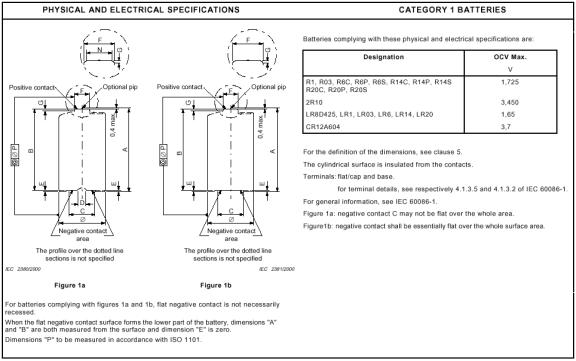
Figure 5:
IEC 60086-2 physical and electrical battery specifications (from IEC 60086-2
page 10).
Table 2: Specified cell
dimensions (all in mm).
|
|
IEC
|
Energizer
|
Duracell
|
|
Ø min. or typical
|
13.5
|
14.5
|
13.5
|
|
Ø max.
|
14.5
|
N/A
|
14.5
|
|
A max.
|
50.5
|
50.5
|
50.5
|
|
F max.
|
5.5
|
N/A
|
5.5
|
|
G min.
|
1.0
|
N/A
|
1.0
|
Suggested Procedures (Hypothesis 2 – Open Circuit
Voltage)
Place your cells into your battery holder. Using alligator
clips, sequential connect wires from the cells to the DMM inputs. Record the
open circuit voltage and compare your results to the IEC requirements and
manufactures specifications. These values for LR6 cells are summarized in Table
3.
Table 3: Open circuit voltage
specifications and expected values for R6 and LR6 cells.*
|
|
IEC
|
Energizer
|
Duracell
|
|
Zn/MnO2 (NH4Cl)
|
1.725
|
>1.55
|
N/A
|
|
Zn/MnO2 (ZnCl)
|
1.725
|
>1.60
|
N/A
|
|
Zn/MnO2 (Alkali metal hydroxide)
|
1.65 max
|
~1.58
|
1.5-1.6
|
*Energizer/Eveready distinguishes between Zn/MnO2
batteries with NH4Cl and ZnCl electrolytes while IEC does not.
Energizer/Eveready considers Carbon Zinc to be a generic term that describes
both systems. They use the term LeClanche for batteries having a
slightly acidic electrolyte of NH4Cl and ZnCl in water. They use the
term Zinc Chloride for batteries having a slightly acidic electrolyte
consisting mainly of ZnCl in water. Duracell produces only alkali metal
(specifically potassium) hydroxide cells.
Suggested Procedures (Hypothesis 3 – Service Life)
These procedures will have to be conducted over multiple
days (possibly over a week) and will take a little over an hour each day. Your
team should plan accordingly.
The service life is defined as the time (in hours) required
to reach the cutoff voltage during the discharge of a cell or battery under
specified conditions (duty cycle, load resistance and temperature). Specified
cutoff voltages are summarized in the Table 4, in which all numeric values are
in volts.
Table 4: Standard and specified cutoff voltages for
LR6 cells.*
|
|
IEC
|
Energizer
|
Duracell
|
|
Zn/MnO2 (NH4Cl)
|
0.80
|
0.75
|
N/A
|
|
Zn/MnO2 (ZnCl)
|
0.80
|
0.75
|
N/A
|
|
Zn/MnO2 (Alkali metal hydroxide)
|
0.80
|
0.90
|
0.80
|
*IEC uses 0.8 volts for motorized toy tests and
0.9 volts for other tests.
Measure the actual resistance of each nominal 3.9 Ω
resistor and place them into your Circuit Designer such that the association
between individual resistances and battery numbers are known. These are your
load resistors. During each daily discharge period (I expect there will
be 8 or 9 of these):
Measure and record the open
circuit voltage of each cell.
Connect each cell to a resistor. Note which cells
are connect to which resistors so that average currents can later be
calculated.
Immediately measure and record the
closed circuit (under load) voltage of each cell.
Every 10 minutes, repeat the
closed circuit voltage measurements.
At the end of 1 hour, make a final
close circuit voltage measurement and disconnect the cells from the load
resistors.
Immediately measure the open circuit
voltage of each cell.
Cells are considered to have
reached the end of their service lives the first time their closed circuit
voltage drops below the cutoff voltage. Note that cells will have two service
life values. One based in the IEC standard and one on Energizer’s own, more
stringent, standard. For comparison purposes, calculate Energizer style service
lives for Durcell cells and Durcell/IEC style service lives for Energizer
cells. Use linear interpolation to estimate the service life of each cell to
within 1 minute. Note that only the time that cell has spent under load are
considered in service life calculations. The IEC 60086-2 standard specifies a
minimum average service life of 4.0 hours for LR6 cells discharged through a
3.9 Ω resistor for a period of 1 hour/day. Compare your results to this
standard.
Suggested Procedures (Hypothesis 4 – Service Capacity
Comparison)
Use your data from the Hypothesis 3 procedures to estimate
the service capacity (in terms of energy and charge) of each of your cells.
Compare these results to the manufactures’ specifications that are listed in
Table 5. Compare the average values for each brand of battery. Is there any
difference. You will need to use material on numerical integration and
statistics to be presented latter in this course to complete these procedures.
Table 5: Specified service
capacities for LR6 cells.
|
|
Energizer
|
Duracell
|
|
Joules
|
n.a.
|
n.a.
|
|
mA-hrs
|
28501
|
n.a.
|
125 mA continuous drain to 0.8 V cutoff. Note
that this is not the same as the discharge conditions in the IEC standard you
used.
References:
Anonymous. Primary
Batteries – Part 1: General (IEC 60086-1). Geneva, Switzerland: International
Electrotechnical Commission, (2000).
Anonymous. Primary
Batteries – Part 2: Physical and Electrical Specifications (IEC 60086-2). Geneva, Switzerland: International
Electrotechnical Commission, (2000).