This is an individual lab
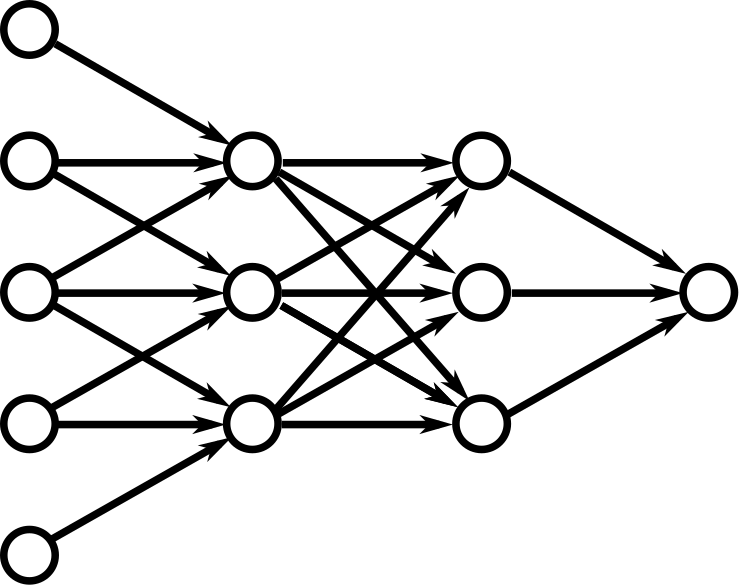
A feed-forward neural network is a network in which the signal enters at the left, flows through the network, and exits at the right without looping backwards on itself. An example network is shown here:
The network above is organized into layers:
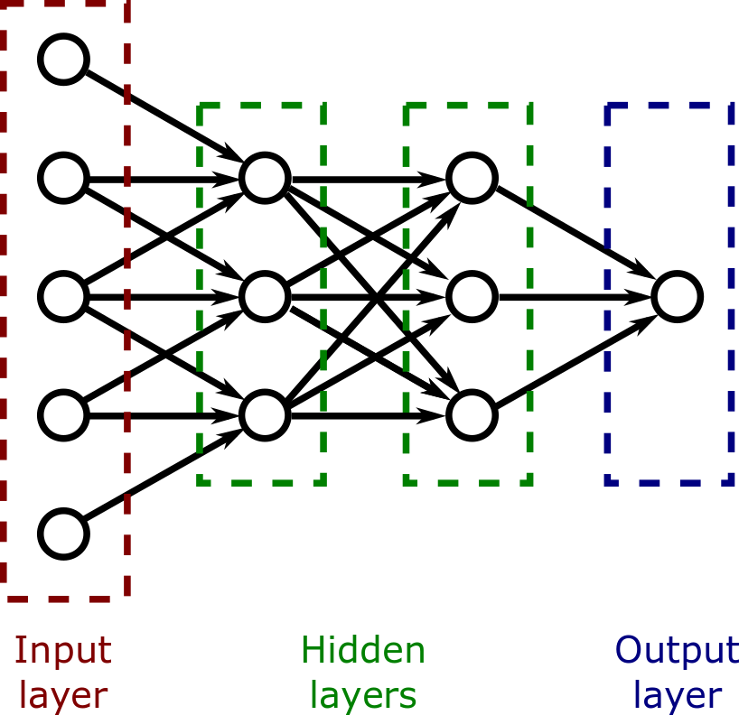
The values of the input layers, on the left, come from some external data such as the pixel values in an image or the audio samples from an audio stream. The value of the single node in the output layer indicates a decision. If the value is high, it could indicate that the image contains a picture of a cat, and if the value is low, it could indicate that the image contains a picture of a dog. The middle two layers are called "hidden layers." A deep neural network is a network that contains many hidden layers.
In this lab, you will write a program that draws the structure of a neural network. When you complete the lab you will understand the decorator pattern and how it can be useful in applications such as neural networks. As a by-product, you will also understand the basic structure of common neural networks, which is an essential step if you wished to implement your own deep neural networks. At the end are some "just-for-fun" ideas to move your lab closer to a real implementation.
The key idea we will employ in this lab is that a neural network is layered. We can consider each layer to decorate the layers of the network that come before it:
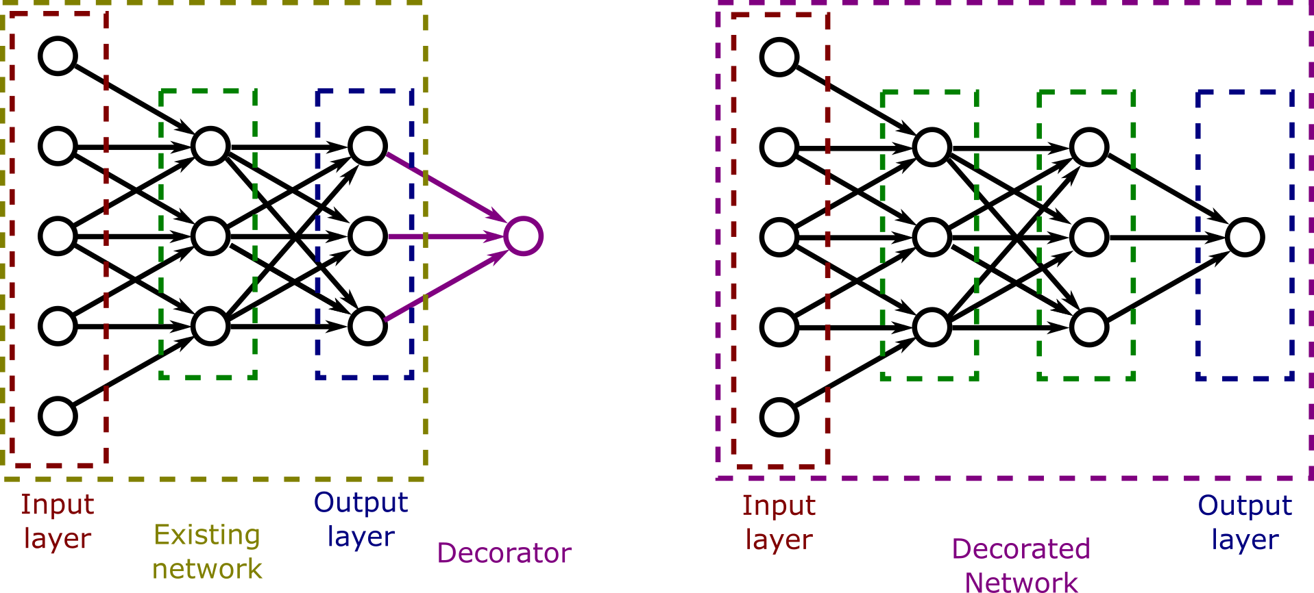
The decorator takes the output of its network as its input, and the output of the decorator is the output of a new network: The decorated network. The decorated network has the same inputs as the underlying network, but produces a new output by adding one layer to the underlying network.
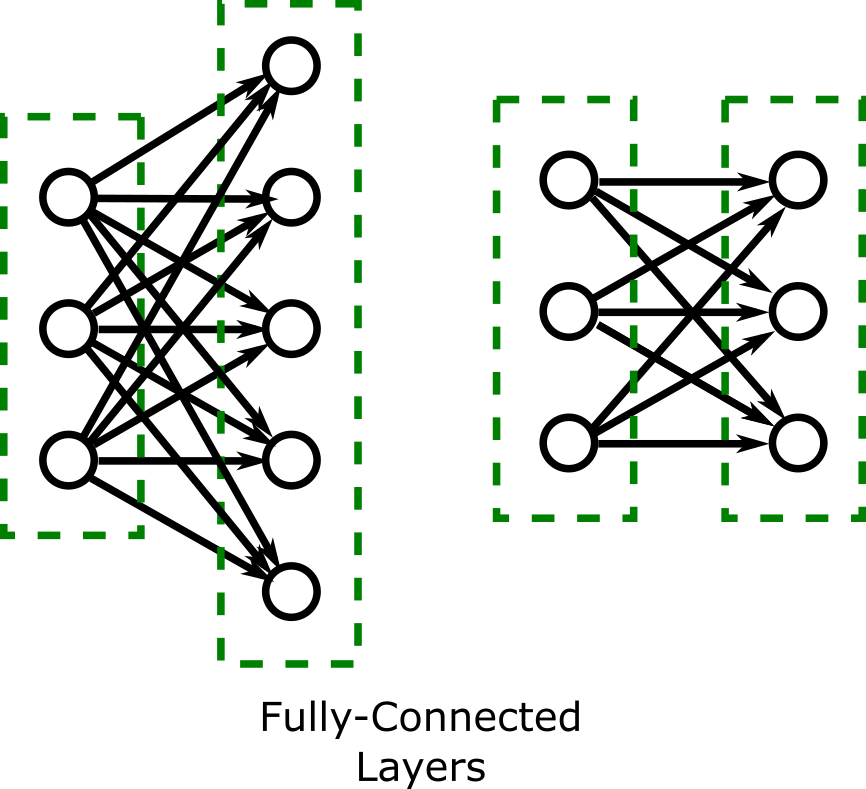
There are two types of layers that we will implement in this lab:
The figure below shows how the fully-connected layer changes when the user (client code) selects a layer size of five or three.
The figure below shows how the 1x1 convolutional network always has the same output size as the input size:
Every layer decorator needs an existing network to decorate. To give the first decorator a network to decorate, a simple concrete decorator network representing just the initial input layer should be written. The outputs of this network are simply the inputs that are given it without modification. (This 'transform' is called the identity transfor, and so you may wish to call this an identity network.) When this network draws itself, it should simply draw a single row of nodes, without any connections between them: (The user (client code) should be able to specify how many nodes when constructing the network.)

The horizontal distance and vertical distances between nodes should be fixed constants so that all of the example networks can be see on a 700x900 screen. (Temporarly changing your display settings is a good way to check this.)
Design a JavaFX program to allow the construction of neural networks. Use the decorator pattern as described above. Draw a contract-level UML diagram illustrating the decorator class and including key methods that you plan to implement. (You may end up choosing to change some methods in the 'contract' as you work through the lab. Be sure to note these changes as you make them an in informal report document.)
Each network should have a draw() method that draws itself on a provided JavaFX canvas. Each network should also have inputSize() and outputSize() methods that get the number of nodes in the input and output layers of the network. It should also include a numLayers() method that returns the number of layers within the network. Include a method on the diagram everywhere you plan to include it in the source code.
In the provided code plan on update the createInception() and createAlexNet() methods to construct two networks: (Note that these are CLIENT CODE that use the decorator classes to construct the desired network.)
During the initial lab period, demonstrate your UML diagram to your instructor and begin your implementation as well.
An example driver is provided which sets up the GUI and has buttons to call each of the methods named above and the draw() method when appropriate. (In Dr. Yoder's section, I hope to provide an example repository through GitHub classroom that you can use both to work on and submit this lab.)
The provided code also gives examples of how to draw edges and nodes on a JavaFX canvas. During your design stage, please decide where you will move these methods and associated constant. They should NOT be a responsibility of the controller.
You could also choose to implement these additional layers:
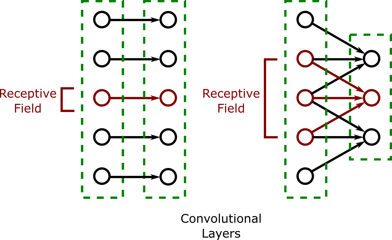
As illustrated in the figure below, In an nx1 convolutional layer, each output node is aligned with the center of its receptive field. An output node is only included in a convolutional layer if all the nodes in its receptive field exist in the previous layer. This determines the size of the convolutional layer.
The number of nodes in the receptive field must always be an odd number. Raise an exception if the construction of a layer with an even-sized receptive field is attempted.
The figure below shows how the size of the network changes as the user (client code) selects a receptive field of size one and a receptive field of size 3.
To convert your network into a real neural network, you would need to asign weights to each arrow in your picture, add activation functions such as the ReLU at each node, and adjust the weights during training with backpropagation. There are a couple of small steps in this direction you may enjoy.
Illustrating edge weight: In a neural network, each edge has its own weight. A simple way to illustrate this would be to give each edge in the network a different random thickness. Training the network so these thicknesses are meaningful may well be beyond the scope of a "just for fun" exercise.
Illustrating activation functions: In a neural network, each node has a nonlinear function that it applies to the sum of its inputs. This is critical so that the whole network's output does not collapse to a single matrix multiplication on the inputs. You could illustrate this by drawing the two lines to illustrate the ReLU's graph inside a node. (Or a sigmoid, if you are into those.)
In Dr. Yoder's section only, please see the submission instructions in my answer to this Stack Overflow question