This is an individual lab. You may get help from other students, but you should do the lab yourself without copying work from another student. You may, however, ask other students for help by describing problems you are encountering and asking them to describe how they overcame the problems. If you are looking at their solution while working on yours, that is a problem.
Follow the prelab and lab instructions as listed on Dr. Meier's page for this assignment, noting these additional requirements and hints:
Prelab
The instructions specify to
The instructions specify to work the schematic tutorial and FPGA programming tutorial (both linked from the bottom of the Design Software Page). While working these tutorials, you do not need to create the prime circuit shown in the lab handout. You can instead choose one of the circuits required for the lab.
In addition to working through the tutorials for one of the circuits, you should also
When naming files, don't start a name with a number, and don't include a dash anywhere in the name. This breaks the simulation tool. (Thanks to Dr. Ross for this tip)
If you decide to rename a schematic file, Quartus will not find it when compiling. To tell Quartus where the new location of the file is, follow these steps:
- Open the project
- Open the BDF schematic file. Make sure you click in the BDF file so that it is active.
- Use the menu option Project -> Set as Top-Level Entity
Make sure to remove all visual noise — anything that distracts the eye from the important parts of the circuit. This includes uneeded corners or kinks in the wires, etc. To get rid of little pieces of wire ending in "X," click exactly on the x, and drag it to the start of the wire. The wire will disappear.
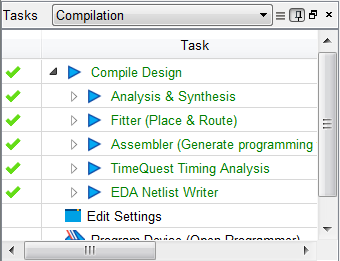
To ensure that the circuit has compiled succesfully, look at the task pane on the left side of the screen. It should have all check-marks:
When plugging in the USB to your board, be sure to plug it into the position indicated in the image in the text -- the end with the power supply. It will fail with mysterious errors if you plug it into the other end.
If you encounter problems during this process, please feel free to email me or stop by my office hours. If you have hints that you wish to share with the rest of the class, I can post them here. If you get stuck part-way through the prelab the night before lab, start early next time. And go to bed. It's OK for this first lab.
Turn-in instructions
You can actually complete most of the lab before lab. I recommend doing everything except the final printouts. You may want to do that too, just to check that you have everything you need.
I will bring printouts of the Lab Grading Checklist to lab. Include this page, along with the printouts it describes. The due-date and turn-in instructions are also printed on this checklist.
Whenever you print out a simulation result, be sure to mark it up to demonstrate that it meets the requirements. Draw arrows to where you would point while describing it to me, and hand-write text explaining how that part of the simulation result demonstrates that the circuit meets the requirements. This week, the requirements are simple to see in the simulation results. But in future weeks, you will see different kinds of requirements. For example, if you are given a mystery circuit and not told what it should do, you should demonstrate that what it does is correct based on the gates used in the circuit itself.
There are partial verions of "compile" available that can speed things up. The "Start Analysis & Syntheses - Ctl+K" button two buttons down from the Compile button will do the same thing as compile, but stop before assigning the pins. So if you haven't assigned the pins yet, you can save some time by using it instead of the full Compile.
When creating a project, be sure to create a folder for the project. Qurtus does not do this automatically. You can open the file explorer, and follow the step-by-step instructions given in the lab handout. You can also right-click in the file open dialog and create a folder that way. But however you do it, be sure to make the folder
Be sure to NOT put your quartus files in the directory that quartus names. As the lab suggests, put the folder somewhere else. I suggest not having any spaces in the path to your folder (Some programs break up a path into two parts if there is a space in the middle -- you can imagine what kind of trouble that might cause!). You can make a shortcut to your folder and place it in Quartus's default directory. That can make it easier to jump to your folder.
To re-open one of your Simulation Waveform Editor files, go to File->Open as you would expect. Then, type *.* where you would usually type the filename. This will cause hidden files (like the vfw file) to appear. Click on your waveform file to open it. Although the configuration of the simulation (pins, counting) si saved, the simulation results are not. You will still need re-run your simulation to get the results.