This is an individual lab. You are expected to do all of the lab on your own. While you are free to discuss the lab with other students, you should not show your own solution to other students or look at theirs. This includes not only code, but also the diagrams and analysis. However, you are free to discuss your solution technique and even demonstrate it using examples different from the ones in this lab. Please allow other students the maximum opportunity to gain experience on this lab by working it themselves, and please work this lab yourself
A printed copy of the Lab checklist will be provided.
Introduction
The purpose of this lab is to gain familiarity with basic circuit principles, including predicting voltages and currents in series and parallel configurations and tips for not damaging the Beaglebone.
Equipment Needed
- Your beaglebone black
- SE3910 Kit (Checkout from Tech Support)
- USB Oscilloscope (Digilent Analog Discovery)
- Beaglebone Breadboard Cape
- (optional) Beaglebone Breakout Board
- A few 2.2 KΩ resistors (Checkout from me)
Documentation and Resources
- Beaglebone Black
- USB Oscilloscope (Digilent Analog Discovery)
- Google and download: Digilent Waveforms 2015 (or follow link, if it works)
- Analog Discovery Pinout (Original source: Digilent website)
- In the Spring 2016 quarter, a couple of students had the Analog Discovery fail to connect, even though the USB device was showing up in the Device Manager, and even though the drivers were already installed. To correct this problem, they went into the Device Manager, and manually pointed the driver to
C:\Program Files (x86)\Digilent\Runtime\UsbDriver.
- SchemeIt -- Free online schematic drawing tool from digikey
- If you want your Beaglebone to be able to access the internet through your computer through the USB, these instructions have worked for a student in the past.
- LED specifications
- The Beaglebone Breadboard includes an LED. The Wiki Documentation specifies that the voltage across the LED is 2.12 V. (And this is the voltage whether there is 1mA or 50 mA through the LED). This is probably the specification for this LED (just a guess...)
Prelab
Read through the Lab Procedure. Do what you can without the hardware.
Also, fill out the Lab 2 Report as much as you can: Write the introduction, and analyze each of the circuits to determine what voltages you expect to measure in lab.
Finally, optionally, you can draw your circuits as they would appear on the Breadboard or Beaglebone Solderless Breadboard. (The beaglebone solderless breadboard cape is not available in every SE3910 check-out kit.)
Lab Procedure
Getting familiar with the Waveform Generator and Oscilloscope (DC — direct current -- i.e., constant voltages)
Install Digilent Waveforms (see above)
Plug the Analog Discovery into your comptuer using the included specialized USB cable
Start->All Programs->Digilent->Waveforms
If no scope is plugged in, you can select Demo Discovery to open a simulated Analog Discovery with some default signals coming in. This is enough to get somewhat familiar with the interface before you come to lab.
Under Analog, open both Scope and WaveGen.
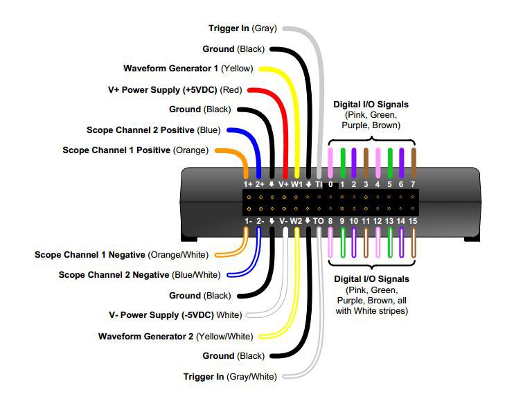
When you have real hardware, connect the Channel 1 to the Generator 1. To do this, connect 1+ (Orange) to W1 (Yellow) and 1- (Orange/white) to Ground (black). The figure below may be helpful.
Set waveform generator 1 to a constant voltage. In the list of waveform icons, click on the flat horizontal line.
Change the drop-down with the value "Simple" to "Basic" to show sliders on the inputs.
Drag the "Offset" slider up and down (from -5 to 5 Volts). In the scope window, you should see the line moving up and down as well. The scope is designed to track changing voltages. You may find that it doesn't update for relatively constant voltages, like we use in this lab. To get it to update better, in the top right corner of the Scope window, confirm "Condition" is "Rising" and set "Level" to "5 V", and "Mode to "Auto." Don't use autoset -- it' doesn't work well for constant voltages, either. But you may find some other settings to be helpful.
Set the voltage to 1.5 Volts. In the scope window, you should see the line intersecting the vertical axis at 1.5 Volts as well. You may want to try out some other signals to get a better feeling for how the scope responds.
To make reading values easier, you can click on the graph, which will insert a vertical red line reading off the values of the signals. You may find it easiest to read these values if you stop the scope.
The circuits
Before lab, work through the handout and predict both the currents and the voltages for each circuit.
In lab, wire up the circuits and test them to see if the voltages are what you expect.
In place of the power supply, for the circuits that don't use GPIO, use the waveform generator's W1 with a DC (constant) "wave" set to 3.3 V
In place of the power supply, for the circuits that do use the GPIO, use the 3.3 V pin from the "Basic Proto Cape"
Don't use a cape plugged into the beaglebone until you've done all the off-beaglebone circuits. This reduces the risk of damaging the beaglebone.
To connect any two wires together, plug them into the same row of the wireless breadboard, as in the in-class examples. I'm happy to help with this.
Record the measured values in the provided spots in the lab report. Compare this voltage with what you predicted, and correct any errors in your initial prediction or experimental technique. Note that the voltage drop across the LED can be quite different from the specifications. So a different measured value does not necessarily mean your calculations are wrong.
Beagelbone Pinout
The Beaglebone pinout is:
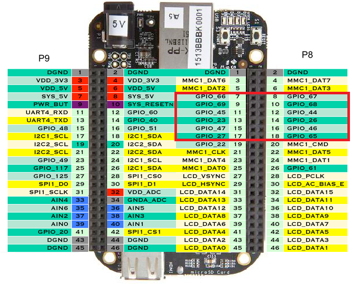
When using Bonescript, you can refer to the pin directly in the order you wire to it on the Beaglbone headers: "P8_19" is pin number 19 on the P8 header.
Excellent Credit Ideas
- Wire up the LED to a Beaglebone GPIO pin, and control it with some Bonescript.
- In Circuit 7, you supply an input to a GPIO pin. Why not wire up both switches, some LEDs, and make a little program that responds to user presses?
- What do you think would happen if a pin is set up as output, but used as input? How about if a pin is set up as input and used as output?
Mention your excellent-credit work in your conclusions. You may want to include an extra sheet in your report. That's fine.
Demo
Demo a circuit half-way through the lab (whatever circuit you are working on)
Demo the last circuit you work on in lab (This may be your excellent credit circuit)
Turn-in
Fill in all blanks, including the introduction, and conclusions, unless stated optional or Excllent Credit (EC). Staple your report. You do not need to fill in your name at the bottom of each page - on the front is fine.
The demonstrations are due during lab. The lab report is due 9am the following class day. You can slide it under my office door or put it in my mailbox in the EECS office.