This is an individual lab. You are expected to do all of the lab on your own. While you are free to discuss the lab with other students, you should not show your own solution to other students or look at theirs. This includes not only code, but also the diagrams and analysis. However, you are free to discuss your solution technique and even demonstrate it using examples different from the ones in this lab. Please allow other students the maximum opportunity to gain experience on this lab by working it themselves, and please work this lab yourself
Check out your equipment with your drivers license, since you will need your MSOE id to print out your final results. If you do not have a dirver's license, make screenshots, check your screenshots with me, check back in all your equipment, and then print and mark up your screenshots.
A printed copy of the Lab checklist will be provided.
If you have any difficulty with Linux, the VM, the Beaglebone, or Networking during this lab, check out the SE3910 Tips Page. (You may find these tips helpful even if you don't have any trouble.
Prelab
Read through the Lab Procedure. Do what you can without the check-out hardware:
Also to do before lab:
- Download and install several large files -- a good thing to do in the background while you work on something else.
- Install and run the virtual machine
- Flash the new beaglebone image on the microSD card.
- Boot the BeagleBone from the microSD card and ssh into it.
sshinto the beaglebone from the virtual machine- Succesfully cross-compile the example code and run it on the Beaglebone.
Please demonstrate all your pre-lab accomplishments at the beginning of lab.
You do not need to use the VM, but you must compile the code on a laptop and run it on the BeagleBone black.
You may want to use Linaro with Mac OSX or with Windows. Students have had success with Linaro+Mac OS X and Linaro+Windows, though not necessarily with the link shown here.
Introduction
In this lab, you will re-image your beaglebone, set up a virtual machine, and start some basic development with a cross-compiler system.
The virtual machine is the platform Derek Malloy (author of Exploring Beaglebone) recommends for cross-compiling code for the Beaglebone. Some students in the past have had success with Windows libraries instead... you are free to try this, if you like. I haven't gotten the Windows libraries to work, myself.
When using the virtual machine, we need to connect through a wired network connection rather than the USB. So you may want to connect your Beaglebone through the wired network as you start this lab.
Virtual Machine setup
To develop for the Beaglebone, we will use a Debian virtual machine.1
The Linux distribution you are using will execute using the VirtualBox virtual machine software. You will need to download this and install the VirtualBox software on your laptop (latest version will work ). You will need to install the appropriate version of the software, which is 64 bit for the MSOE machines.
When you have completed installing Virtual box, you will need to download and install the SE3910 virtual machine image prepared by Dr. Schilling.
I'll give the link in just a moment. But first, note that you need to make sure you check the "Reinitialize the MAC address of all network cards" checkbox as in the image below. This avoids the issue of multiple machines on the network having the same MAC address -- and the mysteriously broken connections that come with it.
Also shown in the image below, when asked where to install your disk image, choose a hard-drive with at least 10 GB of free space! For example, I replaced the default value of C:\Users\yoder\VirtualBox VMs\SE3910 Virtual Machine Student Baseline\SE3910 Virtual Machine Student Baseline-disk2_1.vmdk with D:\VirtualBox VMs\SE3910 Virtual Machine Student Baseline\SE3910 Virtual Machine Student Baseline-disk2_1.vmdk since I had much more space on my D drive than my C drive.

Before you use the system, configure your network settings to use a bridged network adapter. The easiest way to do this is to start the VM with an invalid network configuration. If you do, you will get an error message like this
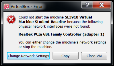
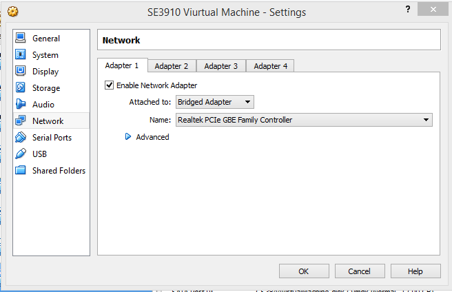
Then you can click "Change Network Settings" and it will take you to the right configuration page, as shown in the figure below. If the warning dialog doesn't appear for you, you can find it through the menu Devices->Network->Network settings.
It can be difficult to choose the ethernet you want from the list. The correct ethernet connection may contain a keyword like "Ethernet" or "Gigabit" and will not contain the keywords "Linux," "USB," "VirtualMachine," or "VM."
You will want to come back to the "Network Settings" dialog to switch your bridge from the Wired to Wireless networks.
While powering on the VM, you may also get this error:
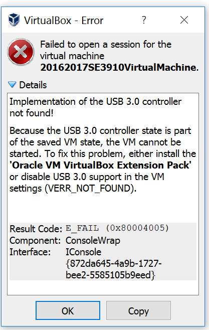
To resolve this error, go to the VirtualBox latest version download page and after the text "VirtualBox Extension Pack", click on the link "All supported platforms"
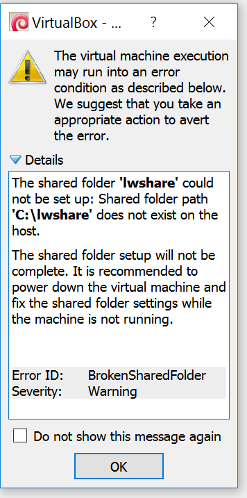
You may also get an error about the share not being set up. You can ignore this error. We will discuss setting up shares later on.
Once the Virtual machine is downloaded and setup, log onto the operating system. The default user is se3910, and the default password is student.
You should be able to copy-paste data between the VM and your OS since guest additions software should already be installed on the virtual machine.
Create a shared folder between the windows workstation and the virtual machine (From running VM, menu Devices→Shared Folders). Be sure to check "Auto-mount" and "Make permanent" when you set up the folder so you don't have to do it on each boot. This shared folder allows you to share data between the two operating systems as well as reliably back up you work from the virtual machine. You can use any location that you would like for the share point. Useful shares might be the entire D drive of your laptop, the Box.com folder if you use Box.com to automatically back up and synchronize your data, or a subfolder of your personal SE3910 folder (Dr. Yoder: I prefer the latter for my own work).
Depending on how much RAM you have, you may want to scale back the amount of RAM used by the virtual machine. I scaled back the RAM usage to about 1.5 GB on a 4 GB machine. The default of 2GB works fine on my new 8 GB machine.
If your shared folder is named vmshare, it will show up in the VM at /media/sf_vmshare. The location on the Windows side is whatever full path you specify while setting up the folder.
Creating your bootable flash image
Either after or before installing the virtual machine, you will need to make a bootable flash image for the Beaglebone Black. To do this, you will need the microSD card that came with your Beaglebone from Tech Support. This card will serve as your Beaglebone's "solid-state hard drive." In the event that your Beaglebone operating system becomes disabled, you can repeat these steps to restore your Beaglebone to a bootable state.
- Download and install the Win32DiskImager software. (This software is also linked from the Beaglebone start page. This software will allow you to burn an SD card from windows with a binary image.
- Download the Beaglebone image file. This is about a 0.68 GiB download).
- unzip the Beaglebone image file (e.g. with 7zip or another extraction program). The default install of 7-zip does not always work to unzip the .xz file. You may need to download 7-zip from the official website to get this to work.
- To burn the image, insert the SD Card into a MicroSD card adapter or a USB to micro SD card reader. Pay extreme attention to where the drive is mounted. It is highly recommended that you remove any and all extra storage media from your machine.
- Start up the Win32Disk Imager software. (The EXE installs under "All Programs -> Image Writer.") Select the image file in Win32DiskImager. Also select the destination drive. When you are ready, press write and the disk image will be written. Writing the image will take about 5 minutes. Or much more. Your Mileage May Vary.
- Confirm from the VM that you are able to connect to the internet. Open a command prompt by right-clicking on the background and selecting "Open Terminal Here". Then type
ping google.com. Type Ctrl-C to quit the ping. You should have a 100% successful ping. (0% packet loss).- If you are not able to ping Google, see the help instructions at the beginning of the lab.
Updating the image on your Beaglebone
Once writing the image has completed, you will have a burned image of the operating system on the SD card. With the power to the beaglebone turned off, insert the microsd card into the sdcard slot. Turn on the Beaglebone, and it should boot off of the card rather than the on-board flash memory.
Changing your Beaglebone's name
When your Beaglebone boots, it will, by default, have the name beaglebone. To avoid confusion when multiple beaglebones are on the network at the same time, we want to change it to something unique. To do so, we will ssh into the bone and edit a file.
To do this, open Putty on your Desktop and ssh to root on the bone, as in Lab 1.
On the beaglebone, run the command nano /etc/hostname (or vim /etc/hostname if you like that editor better). This will open up the editor and allow you to change the hostname. Change the hostname of your beaglebone to <yourusername>beaglebone (without any dashes or underscores or angle brackets). Press Ctrl-O to write the file out and Ctrl-X to exit (in vim: type :x and then enter to save & exit).
When this is done, edit the /etc/hosts file on the bone, again replacing the text beaglebone with <yourusername>beaglebone, anywhere beaglebone appears in the file.
With this being done, issue the command reboot (followed by exit) to reboot your beaglebone. Your connection will drop.
Reconnecting to the Beaglebone
The Beaglebone will reboot after you issue the previous command. You should be able to connect to it exactly as you did when changing its name.
Now that you have changed the name on the sd card, you can check that you are booting from the SD card (rather than the on-board flash memory) by checking the hostname. If the hostname is your new name, you are on the SD card. If your hostname is still beaglebone, you are on the flash memory. The hostname shows up after the @ in the prompt.
Connecting to the Beaglebone from the Virtual Machine
In the Spring 2017 term, I was able to connect from the guest VM directly to my Beaglebone through the USB connection. I don't know if installing Wireshark with USB capture support is what enabled this, or if it just worked. My VM was using NAT rather than a Bridged connection.
According to BeagleBoard.org, "[v]irtual machines are not recommended when using the direct USB connection. It is recommended you use only network connections to your board if you are using a virtual machine."
So cable up your board to one of the hardware switches in the lab as follows: The BeagleBone should be cabled to the switch. Your laptop should also be cabled to the switch. (Thanks to Dr. Schilling and several others for doing a lot of work to get these here for us!)
Find the IP address of the BeagleBone on the ethernet switch. (The USB IP address will not work.) There are several ways to do this listed under Internet Tips at the beginning of the lab. Here is one way: Connect to the Bone through Putty and USB to find its IP addresses. Then, from a windows command prompt, find the IP address of your laptop. The subnet of two of these should match. For example, on my system, the bone had one IP address that was 192.168.1.100, and my computer had an IP address that was 192.168.1.103. The switch is acting as a 192.168.1.X subnet DHCP server (It has a subnet mask of 255.255.255.0). When I turn on my virtual machine in bridging mode, it gets an IP of 192.168.1.104, so it virtually appears as another device on the same subnet.
Connect to the Bone through the virtual machine. Open a terminal window in the virtual machine, and type 'ssh root@___.___.___.___', filling in the blanks with the IP address of the bone you found above.
If you always connect your devices to the switch in the same order that you used today (in time, not which port you plug into on the switch), you may find that they have the same IP addresses in the future, which can make this process simpler to work through. The DHCP server might also remember which IP addresses it assigned them in the past, regardless of which order you insert them.
Verifying that C++ programs compile and execute
Once the tools have been installed, open up an editor (e.g. gedit) on your virtual machine and enter the program shown below. This is a simple C++ program that will test out the cross compiler on your virtual machine. Unlike a traditional compiler, a cross compiler will write code for a different platform. In this case, you will be writing the code on your Linux Virtual machine, but it will be targeting the ARM architecture on the Beaglebone.
Sample C++ (arm2.cpp) program for cross compilation
#include <iostream>
int main(int argc, char* argv[])
{
    std::cout << "Hello Dr. Schilling" << std::endl;
}
Once you have entered the program, type the command:
arm-linux-gnueabihf-g++ arm2.cpp -o test2to compile the code. You should see that the code compiles successfully. Try and execute the program on your Virtual machine by issuing the command ./test2. You may receive an error message, or you may not. We are compiling the program to run on the Beaglebone, not the virtual machine, so it doesn't need to work here.
instead of FTP, you may want to use scp test2 root@192.168.7.2: to copy the test2 file to your beaglebone's root user's home directory.
Open up a second terminal window on your virtual machine and change to the directory where the code you are developing resides. Issue the command
sftp root@your.bone's.IP
to connect to your Beaglebone. The password (as is shown on the login screen) is temppwd. Type the command
put test2
to transfer the program to the Beaglebone. Now open a third terminal window and change into the directory where your code was developed. Issue the command
ssh root@your.bone's.IP
to open a secured connection with the Beaglebone. Log on using the temppwd password and type the command
./test2
to run the program. With this program successfully running, we now know that C programs can be cross compiled to our embedded board.
To compile a C program instead of a C++ program, use arm-linux-gnueabihf-gcc instead of the ...-g++ command.
Measuring latency
Latency can be defined as "the time that elapses between a stimulus and the response to it." (And is closely related to response time, if not synonymous with it.) As we design our computer system, there is always latency. In the computer system, the latency is caused by the delay between an input signal changing and the appropriate output action being taken.
We would like to determine the latency between a push button being pressed and the LED changing state. To do this, you will need to copy some files to the shared folder that is accessible by your VM. Thes first file is the program busy.cpp, which sets up an interrupt-driven response to the button in C. This file requires Derek Malloy's GPIO.h and GPIO.cpp (The latest versions are available at Malloy's GPIO github page, though it hasn't changed since the book was published in Dec. 2014 through Spring 2016, so it's pretty stable.) The GPIO.h and GPIO.cpp files are described in Malloy's text, Chapter 6, pp. 214-217. busy.cpp reads the input from a pushbutton, and based upon whether the pushbutton is pressed or not, turn the LED either off or on.
To compile the busy program, on the virtual machine, in a command prompt, use
arm-linux-gnueabihf-g++ busy.cpp GPIO.cpp -l pthread -o busyThere are three ways to refer to a GPIO pin on the beaglebone. In the labs so far, we've used the locations in the P8 and P9 headers. Internally, these pins have a different number (the "export pin number"), as shown in the chart below:
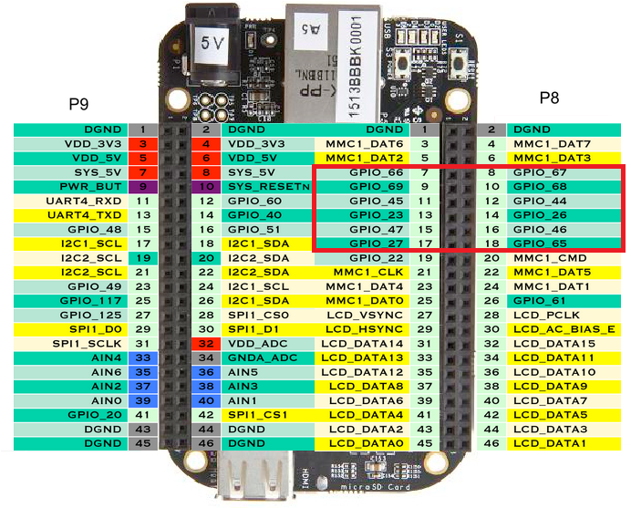
These export pin numbers are the ones used as command-line arguments in this lab. For example, to light up the pin at P9_15, which is export pin number GPIO_48, I would use 48 as an argument to the example program.
In addition to that, the BASIC PROTO CAPE has a different numbering scheme, made up of both a "controller" bank (0, 1, 2, or 3) and a pin number within that bank. export pin number = controller number * 32 + GPIOPin. For example, GPIO_48 discussed above is GPIO 1_16 on the BASIC PROTOC CAPE, since 48 = 1 * 32 + 16
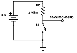
Connect an input switch to a GPIO input port as illustrated in the schematic below: (you can use a 2.2 KΩ resistor or a 2 KΩ resistor. The difference in current will not matter)
Connect an output LED to a GPIO output port as illustrated in the schematic below:
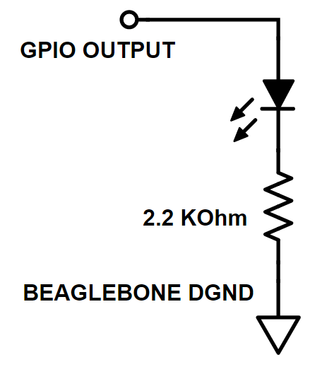
Note that these circuits are separate circuits — they don't share anything in common except the connection to digital ground.
Once you have completed the wiring of these circuits, test the program using the setup that you now have. You should see that pressing the button turns off the light and releasing the button turns the light on.
To measure latency, we will need to change the input ever so slightly as well as connect your Analog discovery device to the unit. We will connect the first oscilliscope channe to the input GPIO pin and connect the second oscilloscope channel to the output GPIO pin so that we can see exactly when the pushbutton is pressed and when the LED changes state.
To capture the very short event, in the top-right corner of the screen, set the trigger to rising (or falling, depending on which event you want to capture — either is fine) and set the the
The figure below shows a sample capture of the oscilloscope in operation. Channel 1 (yellow) represents the output of the signal generator while channel 2 (cyan) represents the output of the LED. Notice the 0.5 ms delay between pressing the button and getting a response.
Here is an example capture showing a measurement of latency:
Please change to a white background before printing: Settings->options. Analog Color. Light.
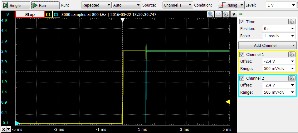
Like this example, your screenshot should have clear round numbers marked on the axis labels. (In this example, ... -1 ms, 0 ms, 1 ms, 2 ms, 3 ms). I recommend setting the Time Base to 1 ms/div or 500 us/div before you capture. If you zoom in on the signal after you capture, it will capture with a lower time resolution.
You should also use the same range for both channels, and see a clear 3.3V signal on both channels.
Once you have set the background to white and printed it, please mark on the chart what the latency your are measuring is.
Measuring a circuit that uses interrupts
Repeat the above procedure with the source code interrupt.cpp, which sets up and waits for an interrupt on the rising and falling edges rather than busy-waiting.
The best solutions will explain the difference in response-time between the two programs.
Deliverables / Submission
Staple the lab check-list to your materials. (This is TBA)
Print off and annotate your waveform screenshot(s). Clear mark how you measure the response time from the figure. It is not necessary to use the digital readout like we often used in Lab 2. Just markup and eyeball the figure.
Make sure you are zoomed in enough to see the difference.
If you have any questions, consult your instructor.
The Fine Print
1Debian has become the defacto standard for those who wish to work with the latest default Beaglebone OS (which is also Debian). If you have used the very-popular linux distribution Ubuntu, the transition will be easy because Ubuntu is based on Debian.